|
 
|
|
Power supply 0.8V-5.0V & Waveform Generator based on AVR
Prototype Features:
- Powered by the microcontroller ATmega32.
- Voltage Range DC: 0.8V - 5.0V in steps of 0.1V. Current 2.5Α.
- Produced waveforms: Sinusoidal, triangular, snaggletooth (right - left) and square.
- Frequency range: Depends on the operating frequency of the microcontroller and the resolution of waveforms.
- Settings are done from 4x4 keyboard and an LCD 2x16 screen, alternatively to power supply only via PC (LabVIEW or TERMINAL).
|
|
Author: Dimitrios Porlidas
Curriculum Vitae
 electronics@porlidas.gr electronics@porlidas.gr
 Facebook Facebook
 Linkedin Linkedin
|
|
|
The project presented incorporates a power supply voltage and a waveform
generator in a simple circuit. It based on microcontroller Atmel ATmega32
(or ATmega16) and the code can be easily modified in order to use
newer microcontrollers that have 4 Ports, External Interrupts, USART
and ADC.
The
settings done by a 4x4 keypad and two push buttons and indicators displayed in
an LCD 2x16 series 1602 screen. The settings of the power supply can also
be done by PC with the LabVIEW through serial port RS232 or USB port with
a suitable converter. The keyboard is connected to PORTB0:7 and the push
buttons to PORTD2:3. Through the keyboard is the choice of operating power
supply or generator and selection of the output voltage of the power supply and
frequency of waveform of the generator. The frequency can also be changed in
steps by the two push buttons.
|
|
The LCD
screen is connected to PORTA1:7 and the output of the power supply is connected
to PORTA0 in order the ADC of microcontroller to read the voltage
output and appearance it on the screen.
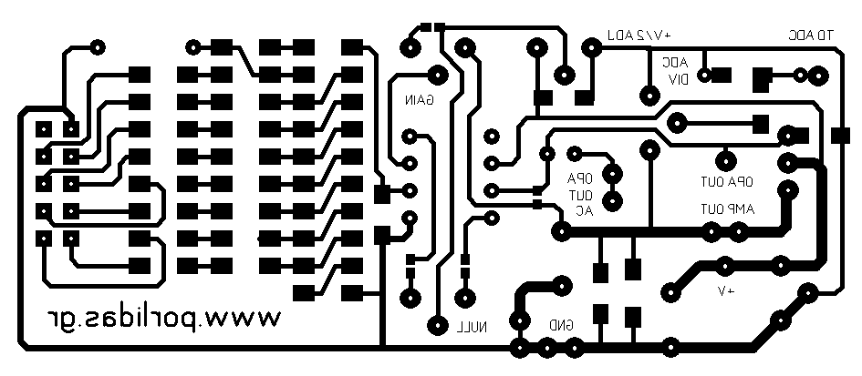
The DAC
circuit is connected to PORTC0:7 and is based on a R2R resistor ladder
network and an operational amplifier. The operational amplifier does not need a negative
supply voltage and with the power transistors are supplied with a
voltage higher than 7V DC (V2). For this reason, placed 2 Zenner diodes in order to
prevent the application of high voltage to the microcontroller in case of
failure. The
feedback to the inversion input of the operational amplifier is the output of
the power transistor in order to eliminate the Vbe. The feedback through R29 is
that it is possible to modify the software to produce higher output voltages.
For the same reason has
been placed R32. R30 has been placed for the Offset zeroing
of operational amplifier.
|
|
|

|
For the
circuit without modifications (as originally designed) the jumpers should be as
shown in the schematic and variable resistors in regulation without voltage
division. The J5
must be closed during operation of the power supply and open during
operation of the generator. The output transistors must be Darlington to be
stable for currents as 2.5A. The accuracy of the output voltage of the power
supply is in the range of 0.05V for voltages greater than 2V and in the
range of 0.2V for smaller, while it is not possible to produce smaller
voltages of 0.8V.
The width
of the output waveform is 2Vpp for sinusoidal waveform, 2.5Vpp for triangular
and snaggletooth and 3Vpp for square, and there is a DC component which can be
eliminated if the waveform received from the J2 (free end of C1) or from the J5
when it is open for the operation of generator (free end of C5). In the first case the maximum
output current is 25mA (depends on the operational amplifier to be installed),
while in the latter case can reach 2.5A and depends on the output transistors.
The DC component is
enough to bring the DAC in the area of operation with optimum accuracy.
|
|
The maximum
output frequency of the generator, for a clock frequency of 4MHz to microcontroller, is about
800Hz for sinusoidal and triangular with 128B resolution, 1.6kHz for snaggletooth
with 64B resolution and 1MHz for square which has a
resolution 2B. Output frequencies can be significantly increased by
increasing the clock frequency of microcontroller. Even more can be
increased if the resolution reduced, which if combined with a
corresponding reduction in output amplitude cannot be at all affected the
quality of the waveforms. Increasing the output frequency must be accompanied by a
reduction in values of the capacitors C3, C4, C6 and C7.
The values
of table for the realization
of the
sinusoidal waveform can be calculated using a spreadsheet (eg
Excel) with the formula = (((SIN (x * 2 * PI () / Res) +1) * Vpp / 2) + DC-Vp )
* 255/5, where Res represents the resolution and x takes values between 0 and
Res.
|
|
|

|
Operating the
instrument is easy. On the home screen is the necessary information for all
functions. Pressing
the A starts operation of the power supply or pressing the B
generator. For the power supply the desired output voltage
consists of one integer and one decimal number by pressing * for
decimal point and then # for execution. If any error, the last
entry cleared with D.
The software
not allow the
introduction of a greater number of 5.0 or incorrect entry but only
in the correct order: [number * number #].The screen displays at
the top line the desired voltage labeled Set: and at the bottom line
the measured labeled Output:.
The
generator is not available to indicate the output frequency (in this version)
but only a division factor of maximum frequency. The entry of the
division factor is the keyboard from 1 to 4 digits and then #
for execution. The output waveform starts and stops by pressing C.
During production of
waveform does not work any other key and there is no other function than
only stepwise decrease
or increase the frequency from the push buttons.
|
|
The type of
waveform can be changed when there is production of waveform by pressing
the * key. The
screen at the top line shows the division factor labeled f div:
and at the bottom line the waveform type and the available keys to their
function. With LabVIEW is possible (in original version) only the control
of power supply. After setting the COM port, the output voltage can be
regulated from the rotary knob or from the numeric indication and
confirmation with the OK button. In Volts field is displayed the output voltage
and there is a lamp, with the characterization Deviation, that lights
when there is deviation from the desired to output value. The tolerance can be adjusted
by the corresponding field in steps of 100mV. The PCB of the DAC is available for downloading. For the circuit of microcontroller
can use the development board presented to the corresponding page. Caution needed in the reception of PORTC because it is the only slot on the board which in
pin 1 is connected PORTC7 and for this reason should be made cable
with reverse turn 1-8.
|
|
|

|

|
|
|
Downloads:
|
|
|
|
Thank you for your support to make my website better.
|
© 2017 Dimitrios Porlidas
|
|
|


