|

|
This
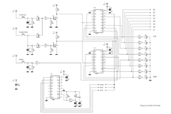
counter designed for use in the development of applications that need a digital
signal of 8 bits, for example decoders, DAC or digital inputs to microcontrollers.
It has optical representation of output with LEDs and 8 pin for connection in
raster. It needs external power between 2V to 18V (recommended 5V).
The circuit
contains two 4 digit counters (CD 4516), a 14 digit oscillator - counter (CD
4060), 8 LED for representation of output, two transistors and buttons to
increase, decrease or reset output. The frequency of counting could be 2, 4 Þ 8 Hz. The digital
value of the output increases by pressing the button [UP], decreases by
pressing the button [DOWN], goes to 0 by pressing the button [RESET] and stay
unchanged when no button is pressed.
|
|
The two 4 digit counters are combining to implement an 8 digit counter by
connecting "Carry Out" of the first counter (IC2) to "Clock
In" of the second (IC3). The "Clock In" of the first counter
(IC2) is connected to one of the outputs of the oscillator - counter (IC1)
through jumpers (JP1), in order to select the frequency of counting. The
oscillator - counter works with an external XTAL 32.768 kHz and its outputs are
from the 4th significant bit and over. The 12th, 13th and 14th significant bit generate a square
signal with frequency f=fo/2^n=32.768kHz/2^n, which is connected to
the "Clock In" of first counter through jumpers, as mentioned
above.
The mode of counting (UP or DOWN) is specified by the status of CL, U/D and
RESET inputs. The signals to these inputs are connected to both counters. Table
I shows the combination of these signals demand for each function, if there is
a clock pulse presented.
|
TableI. Combination of signals for each function.
|
CL
|
U/D
|
R
|
Function
|
|
1
|
X
|
0
|
Stable
|
|
0
|
1
|
0
|
Up
|
|
0
|
0
|
0
|
Down
|
|
X
|
X
|
1
|
All Out 0
|
Clock pulse present
|
|

|
The CL signal activates counting and comes from Q1 which works as a
NOR gate. When one of the buttons pressed, the transistor sets logic 0 to its output,
which was initially in logic 1 because of R9
The state of U/D signal determines the direction of counting. U/D
signal comes from Q2, which works a NOT gate. When the
button DOWN pressed the transistor sets logic 0 to its output, which was
initially in logic 1 because of R10, and activate DOWN counting.
RESET button sets logic 1 to the RESET input of counters and all outputs go
to 0.
|
|
Connecting the circuit:
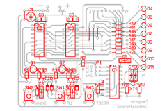
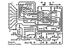
- Connect 5VDC to the board as shown in the back side of PCB by notice the polarity.
- Adjust the desired frequency with jumper (JP1) as shown in the back side of
PCB.
- Reset the counters by pressing RESET button.
- Press UP or DOWN, and keep it pressed, in order to increase or decrease
counting.
Additional information:
-
The value of voltage is not critical. Recommended 5V DC, as it mentioned
above, in order to keep nice lightness and low consumption.
-
Buttons UP and RESET, except the functions that described, are also
jumpers and must not removed or replaced by other type.
|

|
| |
|
|
© 2007 Dimitrios Porlidas
|