|

Figure 1. Current source in battery charger circuit.
|
The Q1 controls the current to the load, which in this circuit is a rechargeable battery. Q2 is
diode connected, and must be in mechanical contact with the Q1 so both have the same temperature. The Q2 together with D1, D2 maintain a constant voltage at the base of Q1 thus maintained constant the voltage at the emitter too. The current i is therefore flowing through the R1 remains constant and it is:


However, since
both transistors are the same type and have the same temperature, they have the same Vbe too. So is valid for
current i:


But ib1 is ‚ times smaller than ic1 and so we can assume
negligible, thus approximately is valid for il
current through the load:

The
current in the load is stable within certain limits. The voltage drop across the
load has to be less than a marginal value depending on the circuit
characteristics:


|
|
If we consider that VD=0.7V and
VceSat=0.2V, is valid:

And if the load has resistance character:


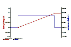
Figure 2
shows a simulation of the flow of current relative to the change of the voltage
across the load in the circuit of Figure 1, wherein it is assumed that the load
is a battery being charged. The voltage supply and the number of diodes depends
on the characteristics of the load and the limitation is to verify the inequality (1). The current through D1, D2 and Q2 must be in the area of 10mA in order to maintain stable the voltage drop
across them. The base current of Q1 (ib1) must be ‚ times less than load current il. The R2 value should be such as to satisfy the above conditions. Therefore is valid:


|

Figure 2. Battery charging in simulation for the circuit of figure 1.
|
|

Figure 3. Current source in battery charger circuit using MOS.
|
The same
circuit can be implemented with MOS transistors exclusively (Figure 3). The
idea of the circuit remains the same as that presented above. To solve the
circuit must be remembered that there is no current flow to the gate of Q1 so
the current flowing through R2 flows through Q2, Q3 too and determines the
voltage drop across them according to their parameters. Thus is formed the
voltage at the gate of Q1. The voltage drop across R1 determines the voltage at the source of Q1 and
so Vgs and current through it. Although Q1 and Q2 have different Vgs , if they have the same temperature, thechanges to the parameters of Q1 with the temperature change will not affect current through it because of corresponding changes to Q2. Q2, Q3 are diode connected and both operate at saturation region because is always valid:

Whereat for the current Id=IR1 is valid:


Solving
the system of three equations with three unknowns can be calculated then the
voltage at the gate of Q1. Q1 must operate in saturation region to maintain the current constant through it, for which is valid:


Solving
the system of two equations with two unknowns can be calculated then the
current through Q1.
|